Oscillating Solenoids

 from Kendrion")


Watch the videos
How our Vibratory Feeding Systems ensure precise material flow

Oscillating solenoids & vibrators for feeding and automation systems
Kendrion – Leading expert in oscillating solenoids & vibratory drives
Kendrion's oscillating solenoids have been proven drive components in vibratory feeding systems, sorting, and conveying technology for decades.
As the market leader in Germany for excitation systems for vibrating drives, we develop customized solutions for a wide variety of customer systems – from compact individual components to ready-to-use drives in various designs.
Thanks to an innovative manufacturing process, our vibrating magnets are particularly efficient: the stacked and pressed laminated core design minimizes eddy current losses, reduces heat generation, and ensures reliable performance. This means that our vibrating drives offer maximum energy efficiency and durability.
Whether operated with alternating current or pulsating direct current, the wide variety of models allows them to be used in a wide range of applications. Particularly compact models are suitable for confined installation spaces, while enclosed versions also impress in demanding environmental conditions.
With functions such as loading, conveying, packaging, dosing, and transporting, vibrating magnets perform key tasks in industrial processes. Typical applications include helical conveyor bowls, funnels, pump drives, and vibrating conveyors.
Wherever precision, efficiency, and reliability are needed – Kendrion delivers.
What are Oscillating Solenoids?
What are Oscillating Solenoids?
What are Oscillating Solenoids?
From a physical perspective, oscillating solenoids generate forced, damped oscillations within a spring-mass system. Their oscillation frequency is specified by the pulsing electromagnetic force of the integrated solenoids (drive frequency). This is always equal to the frequency of the excitation force.
The frequency of the force pulse is determined by the pulsing current in the excitation coil:
- in case of pulsing direct current, this is equal to the pulse frequency of the current.
- in case of alternating current, this is twice as large as the frequency of the alternating current.
- in case of alternating current with half-wave rectification or alternating current with field overlay by permanent magnets, this is equal to the frequency of the alternating current.
Oscillating drives feature several application specifics vis-a-vis other actuating solenoids. The resonance frequency (natural frequency) is the frequency at which a system would oscillate after one-time excitation due to the participating masses and springs alone.
If damping is disregarded, the natural frequency is a single degree of freedom:
F0= (1/2Π) √(c/m) (c...spring constant, m...flywheel mass)
If the units
f0 Natural frequency Hz
c Spring constant N/mm
m weight of free side kg
are used, the following adapted size equation results:
F0= 5 √(c /m) [Hz]
If the drive frequency is too close to the resonance frequency, then an extremely large cycle stroke can result, which will damage the oscillating solenoids.
Further explanations for coordination of the drive with the application are provided in the following sections.
Explanation of terms
Oscillation frequency f | The frequency that the device oscillates at, which is normally 50 Hz = 3000 1/min.
Maximum air gap amax | The air gap indicated on the magnet in the static state
Cycle stroke s | In case of oscillating solenoids, this is the difference between the reversing points of the armature movement in the drive direction.
Useful stroke, side, weight, mass | These relate to the part capable of oscillating that creates a useful effect.
Free stroke, side, weight, mass | These relate to the part capable of oscillating that does not create a useful effect. Ideal case: “Free of oscillations”.
Desired load weight | In case of vibratory feeder drivers as a channel weight, which make installation of a listed device possible.
Nominal power PS, S | The apparent power in case of nominal voltage.
Functionality of the Vibratory Feeder Coils OAC
Functionality of the Vibratory Feeder Coils OAC
Vibratory Feeder Coils OAC
The oscillating solenoids OAC are universally applicable oscillating solenoids for spring-mass systems in oscillating conveyors, linear conveyor drives, etc. to operate alternating voltage or pulsing direct voltage.
The oscillating solenoids consist of the excitation winding, the yoke, and the armature (parts 1, 2, 4), whereby the excitation winding consists of two coils switched in sequence. The yoke and armature consist of magnetic steel sheet (UI section), whereby hysteresis losses in the iron core are kept low. The coils are coated in plastic.
In case of activation with 50 Hz AC, an attractive force is applied to the armature, which pulses with 100 Hz (6000 s/min).
In case 50 Hz alternating voltage is used with additional half-wave rectification, a force pulse equal to 50 Hz (3000 1/min) is applied. Both also apply if the electrical voltage is influenced with a phase angle control (OCS902.000703). With the help of pulse width modulating voltage, the frequency range of 5…200 Hz can be set for the oscillating frequency (frequency control device OCS902.000810).
Functionality of the Electromagnetic Shaker Coil OSR
Functionality of the Electromagnetic Shaker Coil OSR
Electromagnetic Shaker Coil OSR
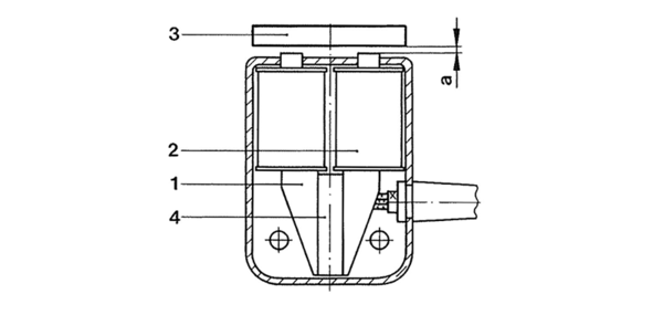
This involves drives for “shaking” components, e.g. using funnels. The magnetic system of the oscillating solenoid is cast inside a plastic housing.
This consists of two excitation windings (picture right, part 2) and two halves of the magnet body, which are connected on the underside by a permanent magnet (part 4). The magnet body is comprised of magnetic steel sheets to reduce vortex flows. The magnetic circuit is closed by the body (part 1) to be oscillated, which indicates the armature (part 3), via the air gap a. If the body to be oscillated does not consist of magnetic material, a magnetising armature plate must be attached. Permanent magnets built into the magnet body pre-magnetise the system, and a constant attractive force results between the magnet body and the armature. If alternating voltage is applied to the excitation winding, the effective force of the electromagnetic alternating field overlays the effective force of the permanent magnet. The frequency of the resulting force therefore corresponds with the frequency of the applied alternating voltage, which moves the armature in the same rhythm.
Functionality of the Electromagnetic linear oscillator OLV
Functionality of the Electromagnetic linear oscillator OLV
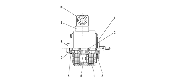
1 Fastening flange | 2 Amature | 3 Spring | 4 Coil 5 | PE magnet 6 Spherical bearing | 7 Spherical bearing shell | 8 Sealing cap | 9 Device plug connector |10 Device plug socket
Electromagnetic linear oscillator OLV
The magnet body of the linear vibrator consists of a round steel housing. The inside of the magnet body features the excitation winding and the armature, which is guided centrally via a non-magnetic shaft and two springs, which are kept in the centre position.
A permanent magnet featuring guiding poles, which is positioned between both coils of the excitation winding, pre-magnetises the system. The forces affecting the armature in this case are compensated by the arrangement of the guiding poles.
If alternating voltage is applied to the excitation winding, the effective force of the electromagnetic alternating field overlays the effective force of the permanent magnet, whereby the positive current half-wave moves the armature in the one direction and the negative half-wave moves it in the opposite direction. Electromagnetic and spring forces complement each other in both movement directions.
Functionality of the Vibratory Feeder Driver OMW
Functionality of the Vibratory Feeder Driver OMW
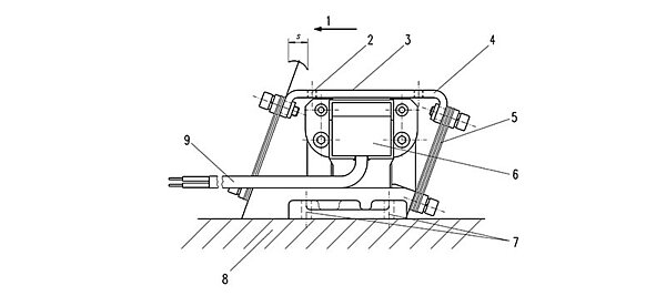
1 Conveyor direction | 2 Thread for fastening the conveyor trough | 3 Useful side | 4 Armature | 5 Leaf spring package | 6 Excitation system | 7 Fastener drilled hole | 8 Free side | 9 Connection cable | s Cycle stroke
Vibratory Feeder Driver OMW
In case of the vibratory feeder driver (Figure 30), the magnet body is fastened to a base with the excitation winding. The armature plate is positioned above this, which features pole surfaces separated by an air gap, which are parallel to the magnet body. The armature plate and the base are connected with each other by angled leaf springs (angle approx. 20°). The coil features an integrated half-wave rectifier (types OMWxxxxx1 …OMWxxxxx3). The type OMWxxxxx4 is pre-magnetised by continuous magnets and works without half-wave rectification.
If alternating voltage is applied to the excitation winding, an attractive force pulsing at the mains frequency results in all types between the excitation system and the armature plate.
Because the leaf springs are arranged at an angle, the armature plate with the conveyor trough fastened on top of it completes an oscillating movement and transports loose material in the conveyor direction. In case of larger or relatively broadly loaded conveyor trough, it is sensible to use multiple smaller devices in place of one large vibratory feeder driver.
Functionality of the Electromagnetic Vibration Generator OAB
Functionality of the Electromagnetic Vibration Generator OAB
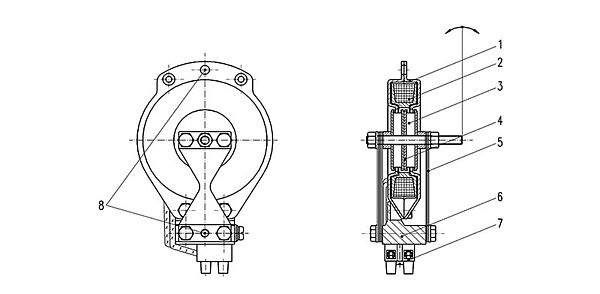
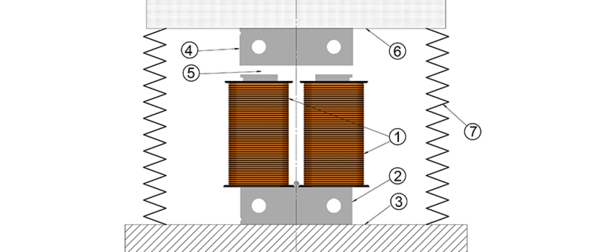
1 Magnet body | 2 Excitation winding | 3 Permanent magnet | 4 Complete armature | 5 Spring | 6 Device base | 7 Connector plug | 8 Mounting
Electromagnetic Vibration Generator OAB
The magnet body of the arc vibration generator comprises two ring shells, which contain the excitation winding. This is permanently connected to the device base. The armature consists of two round permanent magnets featuring axially inverted poles and two pole discs, and it is located between leaf springs that are fastened to the two opposite sides of the device base. The system is pre-magnetised by both permanent magnets. During inactivity, one ring pole is placed between two pole discs each of the armature. If alternating voltage is applied to the excitation winding, the unequal poles of the armature and magnet body attract. The frequency of the arc-shaped armature movement corresponds with the frequency of the applied alternating voltage.
The arc vibration generator may be used as an oscillating solenoid and as a vibrator with an additional weight on the armature shaft.