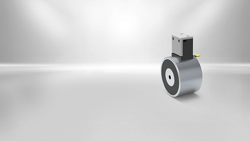
Holding Magnets


Need help choosing the right product?
Our new Product Guide takes you through the process of finding the product you need, step by step. Supported by intelligent questions, the guide will lead you to the perfect match. Finally, you will receive all the technical data and downloads available.
Start Guide for Holding Magnets
Holding magnets – Safe and powerful solutions for industrial applications

In the case of electromagnetic holding magnets, Kendrion differentiates between electro holding magnets, permanent electro holding magnets and door holding magnets. The electro holding magnet consists of a DC-energized coil, which reaches a holding force of up to 30.000N when energized. For long holding especially the permanent-electro-magnet is suitable, since they reach a holding force up to 3.500N in the de-energized state. The Kendrion holding magnets are available both as round pot magnets and as holding bars. Door holding magnets are used in the area of the fire doors. The magnets comply with strict safety guidelines and exist in various designs, each designed for floor, wall or ceiling mounting.
Holding magnets from Kendrion are pot magnets that are used to hold or clamp ferromagnetic workpieces. The electromagnets are preferably used in fixture construction and in the industrial areas automation, transportation and handling. For tasks involving long periods of holding without energy consumption, permanent electromagnets offer advantages. They ensure that a load or workpieces are safely held in the event of a power failure.
What are holding magnets?
What are holding magnets?
What are holding magnets?
Electro-holding magnets (holding magnets) remain able to be magnetised. Workpieces in position due to magnetically created forces. Pieces that are unable to be magnetised are able to be held on a magnetisable armature plate. The specific design of the magnetic circuit maximises the holding force for the smallest possible air gap. The ideal attraction of the armature plate from a greater distance is not available for these devices. The holding force is created by an electromagnetic field in case of electro-holding magnets, or by a permanent magnetic field in case of permanent electro-holding magnets.
In terms of construction, these magnets feature an open magnetic circuit, which is completed by the workpiece and the armature plate. The size of the resulting magnetic flow specifies the holding force. The degree of magnetising ability of a workpiece is specified by the relative permeability μrel of the material.
The larger the magnetic flow Φ for a continuously steady holding surface that penetrates the workpiece, or the greater the magnetic induction B on the holding surface, the higher the holding force FH.
How is the holding force calculated?
How is the holding force calculated?
How is holding force calculated?
The holding force is the force that is required to remove the workpiece from the holding surface of the solenoid. Using Maxwell’s pulling force formula, you may calculate:
FH=B2A / (2μ0)
B...the median flow density in the air gap, A...magnetic holding force, μ0...magnetic flow density of air
In case of a magnetic flow density of 1.6T, approx. 1N result from approx 1mm2 holding surface. The magnetic flow and therefore the flow density are specified by the overall resistance in the magnetic circuit.
What is meant by the Residual holding force?
What is meant by the Residual holding force?
Residual holding force of electro holding magnets
The holding force remaining due to the magnetic remanence after deactivation of the previously indicated nominal voltage of electro-holding magnets. Depending on the workpiece, this is between 20 and 40% of the holding force while the device is activated. In case of door holding solenoids (GTR types), the residual holding force on the armature is overcome by a springoperated pin.
What factors influence the holding force?
What factors influence the holding force?
Air gap δL
This indicates the average clearance between the holding surface of the magnet and the held workpiece surface. The shape of the surfaces facing each other and non-magnetic substances (e.g. galvanic overcoats, paint, soot) form its size.
The roughness and unevenness of the surface acts as an additional air gap. Due to the low permeability of air (μ0), the air gap is the relevant size for the magnetic flow. Influences that affect the holding force:
Configuration of the holding surface
The configuration of the holding surface is the contact surface (in %) that the workpiece contacts the holding solenoids. The holding force per surface unit of a holding solenoid is nearly the same across the complete holding surface. The configuration of the holding surface is at maximum (100%) when the complete magnetic holding surface is occupied by the workpiece.
Material properties
The holding solenoid housing, which guides the magnetic flow, consists of highly permeable steel. For this reason, the high holding force indicated in the data sheets is able to be reached with armature plates or workpieces consisting of steel S235JR (formerly referred to as St37) or comparable materials. In any case, the actual holding force able to be reached is reduced by different application parameters, including the low permeability of the workpiece. This therefore depends on the material type. Hardened materials also possess a lower permeability. The basic rule is: The higher the hardening degree, the lower the magnetic conductance and therefore also the achievable holding force.
Thickness of the workpiece
For every size of device, there is an optimal workpiece thickness, which is indicated in the device sheets of the catalogue as “armature plate thickness”. The associated diagrams specify the influence of low workpiece thickness. An armature plate thickness larger than the indicated thickness, will not result in increased holding force.
Reduction of input power
The input power may be reduced via upstream activation of a voltage regulator. The voltage reduction reduces the heating and the holding force FH of the individual devices.
Special characteristics of permanent electro holding magnets
Special characteristics of permanent electro holding magnets
All of the statements made above apply to both electro-holding magnets and permanent electro-holding magnets, with the exception
- of dependence of the holding force FH on the operating voltage, and
- the expression of residual holding force
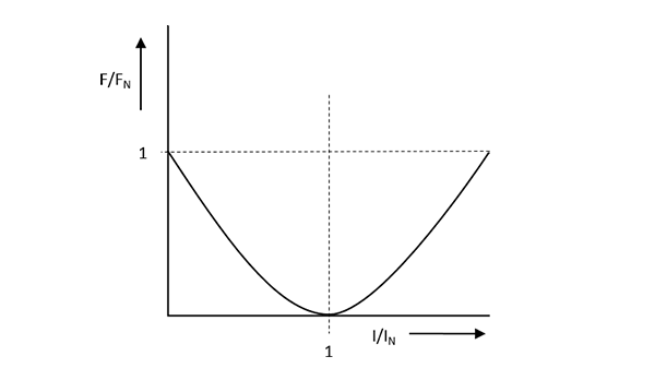
In case of permanent electro-holding magnets, the permanent magnetically produced holding force FH is neutralised by activation of the supply voltage. In any case, the quality of neutralisation depends on the applied voltage (tolerance) and the coil temperature. A holding force FH = 0 N can only be achieved for the exact nominal current.
Figure right displays the size of the holding force FH of a permanent electro-holding magnet depending on the nominal current IN at which the force equals 0 exactly. Depending on the operating conditions, the operating current differs slightly from the nominal current so that a residual holding force FR remains. Ensure that if the current is increased above the nominal current, the holding force will also be too great.