Linear solenoids from Kendrion are universal and cost-effective actuating solenoids ideally suited for use in precision engineering and industrial applications. Common application fields are the transportation industry, energy technlogy and machine building.
Linear solenoids for every requirement
Kendrion has a wide variety of standard solenoids to meet any of your potential needs. All of these solenoids work with the same basic principles of electromechanics, with electrical energy converted to mechanical energy. This is done by energizing a coil causing the armature to move in a linear fashion closing the air gap between it and the pole piece. The armature moves from the stroke start position to the stroke end position. An external force such as a spring is generally responsible for the armature reset. Still, in some cases, like the bistable solenoids, no spring is needed, and both ends can be held using a permanent magnet. Depending on the stroke length, the overall size of the solenoid, the switching times, and the supply voltage needed to operate the solenoid, we have different solenoids that will fit your desired use. For example, most standard solenoids operate using a DC signal, whereas our AC solenoids operate using AC signals or pulsed DC signals. This is just one example of the large variety of standard solenoids Kendrion has to offer.
- High Power Solenoids have long strokes and large forces with low power consumption at their maximum travel
- Reversible Solenoids can be controlled in both directions with two coils included within the housing
- Frame Solenoids are cost effective with tooled housings and small amounts of raw materials used in production
- High Performance Solenoids are compact solenoids perfect for situations where installation space is limited.
- Mono-/Bistable Solenoids commonly called latching solenoids due to their current-free holding abilities at end positions.
- AC Solenoids have an extremely high switching power and long stroke, making the overall size needed for the solenoid smaller than its DC counterpart.
With our standard products comes short delivery times, guaranteed quality, and a large variety of reliable solutions to your needs.
Reach out to our experienced sales team to see what customizations can be done to meet your specifications. Many of our standard products can be adapted to your needs quickly, or if a completely new product is needed, our expertise in the solenoid industry makes us a great partner for you. Get in contact!
What are actuating solenoids?
Neutral and polarised magnets
Neutral linear solenoids are characterised by the fact that they create their magnetic field exclusively via the current flow in the coil. In contrast to this, polarised linear solenoids feature one or more continuous magnets (permanent magnets), which also create a magnetic field without electrical power. With the help of the coil current, the magnetic field of the permanent magnet is modified so that the desired effect is able to be achieved, e.g.
- currentless holding and/or
- reversing the movement direction or
- reduction of power consumption.
Linear solenoids and rotary solenoids
While linear solenoids are used to create linear actuating movements, rotary solenoids are used for rotary drive of a shaft. All explanations of linear solenoids apply to rotary solenoids accordingly.

What is the function of actuating solenoids?
Actuating solenoids should shift a mechanically moveable part with a specified force along a specified path (stroke s).
Spring forces If springs are used in actuating solenoids, they reduce or enhance the externally available mechanical forces.
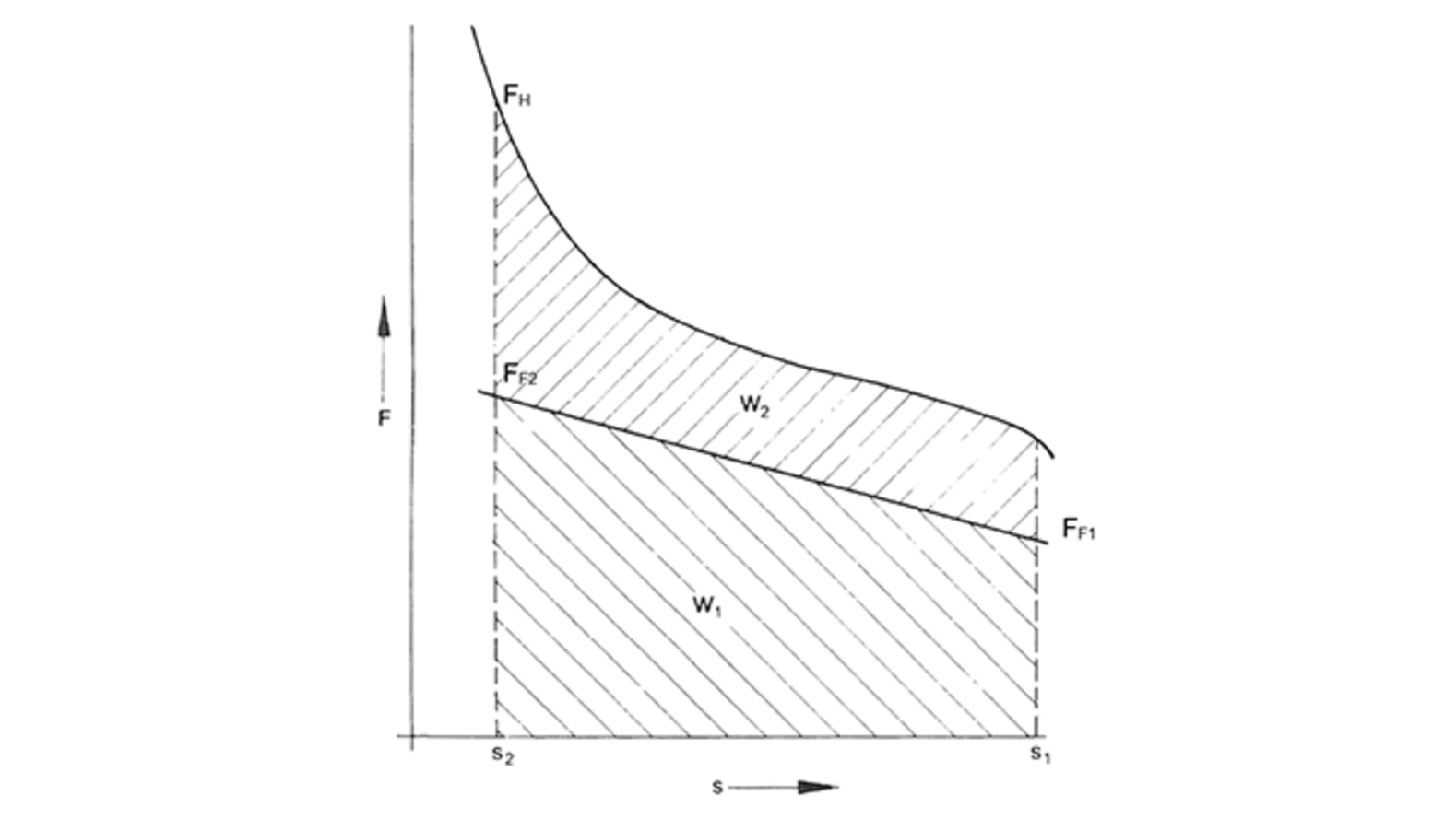
Holding forces In the stroke start or stroke limit position, the armature of the solenoid is able to remain with holding force FH (see figure right). One of these positions is usually held by magnetic forces, while the other forces are held by a spring or other external forces, respectively. Depending on the magnet configuration, the magnetically held position is held via current flow from the coil or by permanent magnets
Armature return movement Prior to executing a new working stroke, the armature must be returned to the stroke start position. This is completed via built-in or external springs or from outside by the mechanical drive that the solenoid is used in. In case of reversible solenoids, the stroke start and stroke end position change with the active working direction.

Which losses occur from abrasion?
Abrasion
The magnetic armature is never exposed to the same forces along its circumference due to geometric asymmetry. Unequally distributed magnetic flow, mechanical asymmetry, and external forces (e.g. gravity) cause bearing abrasion during the armature movement, which lowers the useful magnetic force (Figure right bottom curve). For this reason, the magnetic force FM for the solenoid stroke is given less the abrasive force. On the other hand, the return movement of the armature towards the attraction direction under current requires the force FM+∆FR (Figure right, upper curve). Simultaneously, the bearing abrasion amplifies the asymmetry, and abrasion leads to ageing, which limits the number of movement cycles that may be reached.

What happens during the heating of actuating solenoids?
Heating of actuating solenoids
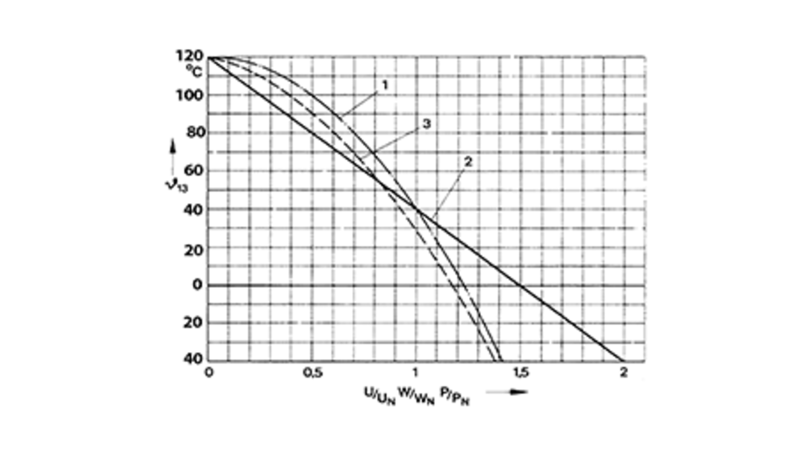
The functions of the actuating solenoids are ensured by the design, assuming standard ambient temperature in connection with internal heating. In case of increased ambient temperatures, reduction in achievable stroke work must be accepted, since the power consumption must also be reduced (Figure right). This takes place to protect the insulating materials against damage.
Additional heat sources
In addition to this, the temperature of the coil is specified significantly by the heat dissipation or addition from the machine components. The good mechanical contact (often metallic, good heat conduction) cause the temperature to be very severely influenced by other sources. In particular, the coil heating during operation must be checked in case of operation on hot components.
How can the optimal magnet design be reached?
To achieve the best ratio of electrical power to mechanical work for a given magnet volume, the ideal design for the underlying power consumption must be determined (in the warm state!).
The optimum level mainly consists of the correct ratio of the coil cross-section (ACu) to the magnetic circuit cross-section.
Furthermore, additional criteria play a role for the ideal configuration, which is why a solenoid is calculated comprehensively and adapted to the individual use case.
What kind of activation processes of actuating solenoids exists?
Operation at the voltage source (normal operation)
Solenoids are normally operated with supply voltage so that the voltage tolerances or internal resistance of the voltage source and lines have an influence on the operating behaviour. In general, these are combined for tolerance-related nominal voltage. Note that the specified upper temperature limits of the coil must be maintained at maximum voltage (→ maximum power consumption) for functionality, but the projected power-force characteristic must be reached in case of minimal voltage and maximum coil temperature.
Heating and voltage tolerance lower the magnetic force of a solenoid significantly below the force at nominal conditions. The magnetic force of the solenoid now amounts to approx. 50% of the force at nominal conditions. The magnetic force of the solenoid now amounts to approx. 50% of the force at nominal conditions. The consequences are clear differences in terms of force, switching time, and activation noise, depending on the level of heat and operating voltage. The forces and switching times indicated in the data sheets are achieved by magnets at operating temperature.
DC voltage controller
The tolerance of operating voltage is clearly limited. For the residual tolerance of ± 2%, for example, and a medium coil temperature of 155°C, the force drops to approx. 60% under warm conditions, compared to nominal conditions.
DC current controller
This voltage is variable for the DC current controller. The maximum permitted current results from the thermal class and the quality of heat dissipation to the environment. The magnetic circuit is optimised to the calculated current. This current can be applied in any operating condition. The supply-side always features a voltage reserve to compensate the increased resistance resulting from heating.
Advantages of current regulation:
- Accelerated activation process
- A maximum solenoid current is specified that is always able to be reached.
- The magnetic force, the switching time, and the switching noise are the same in cold and warm states.
- The magnet may be optimised for the desired force-path characteristic.
A variable current regulation enables solenoids to be used together with a return movement element and/or a path measuring device as an actuator (proportional magnets). In any case, the maximum coil resistance already included during specification of the nominal current, whereby the gained mechanical work is comparable with that of the DC voltage controller.
Shortened activation duration
If actuating solenoids are used in continuous operation, the option of operating with shortened activation duration is available. Due to a changed coil configuration, the nominal power is increased compared to the permanent operation. The advantage related to increased stroke work related to the design size.
High-speed excitation to shorten the attraction time t1
During high-speed excitation the overall resistance is increased via upstream activation of hmic resistance to the magnet, and the time constant is also reduced. The operating voltage UB is clearly higher than the nominal voltage of the magnet UN. During activation (I=0) via high voltage (UB >>UN) with a simultaneously reduced electric time constant
Tel=LM/(RM+RV),
the magnetic coil is excited faster than without resistance. The activation delay time and attraction times are reduced accordingly. In stationary operation with I = IN = const., the operating behaviour and the mechanical work of the magnets correspond with the normal operation.
Note that the preliminary resistance constantly consumes a power loss of during stationary operation.
Over-excitation
In case of over-excitation, the solenoid receives increased voltage during the attraction process to
- shorten the switching time and/or
- to produce increased mechanical work.
Another form of over-excitation consists of initially applying the entire operating voltage to a partial coil (attraction coil (LM1)). After the end of the armature movement, this is connected in series with the so-called holding winding (LM2), so that the nominal current is adjusted.
The difference of "over-excitation" to the operating mode “shortened activation duration” consists of the fact that the power is reduced to a thermally safe value after the attraction process. The solenoid is also able to be operated like a 100% activation duration device. The voltage is reduced either time-controlled or via limit position detection. Because the holding force is present at nominal power by way of the magnet configuration, it is sensible to utilise the over-excitation as far as possible so that the attraction force corresponds with nominal operation.
The increased attraction power causes additional heating during each attraction process, which is why a maximum number of activations Z (switching cycles per h) must be specified for this mode. Over-excitation enables the stroke work to be increased similarly well as by using shortened activation duration, however without the disadvantage of long shut-off phases. The over-excitation power is normally specified so that permanent operation is possible. The theoretical maximum switching frequency therefore results in
fsmax= 1/(t1+t2)
In case of increased over-excitation power, currentless pauses may be required to maintain the temperature thresholds, depending on the switching frequency. These are determined by application-specific tests. The statements regarding the influence of coil warming on solenoid current, force, and activation time apply analogously to over-excitation. Over-excitation can also be combined with current and voltage regulation to produce the advantages indicated above.


